Liquid cooling has moved from niche to essential as AI workloads push compute density and power consumption to new levels. This white paper examines thermal design, architectural choices, implementation steps, and operational requirements for integrating liquid cooling into modern distributed infrastructure. It focuses on practical engineering trade offs and a clear roadmap for deployment in cloud, edge, and hybrid data centers.
Liquid Cooling for AI: Thermal Design and Benefits
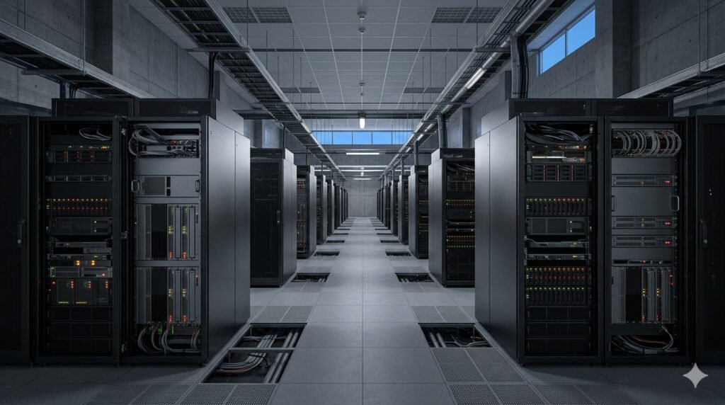
Liquid cooling addresses the fundamental thermal mismatch between traditional air cooling and modern AI hardware. GPUs and AI accelerators now draw several hundred watts each, and dense node layouts produce rack power densities often in the 25 to 50 kW range. Air systems struggle with that density without excessive airflow, high fan power, and large infrastructure footprints.
Direct thermal contact and high-heat-capacity fluids remove heat far more efficiently than air, lowering component skin temperatures and reducing thermal gradients across boards. That efficiency enables higher sustained turbo frequencies and better performance per watt for AI training and inference. Engineers can therefore optimize server layouts for compute throughput rather than for airflow channels.
Beyond peak cooling capacity, liquid systems improve energy efficiency metrics at site scale. By reducing fan energy and enabling higher facility chilled-water temperatures, liquid cooling can lower facility PUE and reduce chiller runtime. The net effect is faster job completion and lower operational cost per AI training epoch.
Heat Density and Thermal Challenges in AI Deployments
AI-optimized servers concentrate multiple high-power GPUs in a single chassis with shared power delivery and cooling constraints. These architectures create hotspots and narrow thermal headroom that compromise reliability if unchecked. Proper thermal design must consider VRM cooling, memory thermals, and localized airflow obstructions within node trays.
Edge deployments compound the problem with constrained space and reduced HVAC capacity. Edge sites often lack raised floors, abundant floor space, or robust chilled-water loops. Liquid cooling variants that minimize site-level infrastructure or operate with air-side heat rejection can make dense inference clusters feasible at the edge.
At hyperscale, the challenge shifts to total facility heat rejection and hydraulic integration. Returning several megawatts of heat to a facility requires rethinking plant equipment, secondary pumps, and heat exchange topology. Engineers must model the entire thermal chain from die to cooling tower to ensure stable operation under variable load and ambient conditions.
Cooling Architectures: Direct-to-Chip, Immersion, Rear-Door Heat Exchangers
Direct-to-chip cold plates provide targeted heat removal and remain the most hardware-compatible liquid approach for existing server designs. They connect via quick-disconnect fittings to a rack-level manifold and transport heat to a liquid loop. This approach minimizes retrofit of server internals and isolates fluid from other components.
Immersion cooling places whole server assemblies in a dielectric fluid bath to remove heat uniformly and reduce the need for fans. Immersion yields the highest heat density capability and simplifies internal server thermals, but it requires validated compatibility of all components with the dielectric and a different service model for hardware replacement and failure handling.
Rear-door heat exchangers retrofit onto rack backs and exchange heat from hot exhaust air into a liquid loop before it enters the data center. This balances low-disruption installation with improved capacity over air alone. Each architecture has trade offs in retrofit complexity, serviceability, and hydraulic infrastructure needs. The table below summarizes key differences.
| Architecture | Typical Rack Power Density | Retrofit Complexity | Service Model |
|---|---|---|---|
| Air Cooling | Up to 15 kW | Low | Standard |
| Direct-to-Chip | 25 to 50+ kW | Moderate | Component-level with fluid lines |
| Immersion | 50+ kW | High | Module-level, fluid bath servicing |
| Rear-Door Heat Exchanger | 20 to 40 kW | Low to Moderate | Rack-level heat exchange |
Implementing Liquid Cooling in Modern Data Centers
A successful implementation begins with a thermal audit and workload mapping. Measure per-node power envelopes, duty cycles, and peak sustained draw. Use those inputs to size manifolds, pump capacity, and heat rejection equipment rather than relying on nameplate assumptions.
Next, define the hydraulic topology and control strategy. Choices include single-phase versus two-phase loops, open versus closed systems, and temperature set points that balance component limits with free-cooling opportunities. Design for redundancy in pumps and loop isolation to support live maintenance and node replacement without downtime.
Finally, integrate liquid cooling with higher-level orchestration and capacity planning. Cooling constraints become another scheduling dimension. The scheduler should be able to place power-hungry jobs into cooled zones and throttle or migrate workloads when thermal headroom is limited. This integration preserves SLAs while maximizing utilization.
Operational Considerations: Monitoring, Maintenance, and Safety
Instrument the loop with flow, pressure, temperature, and particle monitoring at multiple points. Early detection of reduced flow or rising return temperatures prevents thermal stress on hardware. Add per-rack sensors that feed into the facility management bus and into cluster orchestration for automated protective actions.
Maintenance must account for fluid quality, leak detection, and connector lifecycle. Use nonconductive fluids where possible, and choose fittings with visible seals and proven field reliability. Establish a maintenance window cadence for filter changes, fluid sampling, and microbiological testing in open-loop systems.
Safety planning includes leak containment, electrical isolation, and emergency cooling redundancy. Provide drip trays, containment pans, and controlled escape paths for fluid. Ensure staff have procedures and training for fluid handling and that spare parts inventories match the chosen architecture to minimize mean time to repair.
Economic and Sustainability Impacts
Capital cost for liquid cooling can be higher at the outset due to pumps, manifolds, and modified racks. However, total cost of ownership often improves through lower energy consumption, reduced chiller capacity, and higher server utilization. Quantify savings using real workload traces and modeled PUE adjustments rather than simple rule of thumb numbers.
Sustainability gains come from higher facility temperatures and increased free-cooling hours. Returning heat at higher temperatures makes reuse for heating or absorption chillers more feasible. The improved energy efficiency also reduces carbon footprint per compute job, especially where grid electricity is carbon intensive.
Procurement should include lifecycle models that incorporate disposal or recycling of dielectric fluids and the longevity of pump and valve assemblies. A thorough financial model will include CAPEX, OPEX, performance uplift, and potential revenue from heat reuse when applicable.
Infrastructure Roadmap and FAQs
Begin a phased rollout with seven practical steps that reduce risk and capture quick wins:
- Conduct a thermal audit and workload power profiling.
- Run a small-scale pilot with a chosen architecture and measure real-world metrics.
- Design the hydraulic and electrical integration with redundant paths.
- Update deployment orchestration to account for thermal zones.
- Implement monitoring and alarm routing into operations.
- Validate maintenance procedures and spare parts lists.
- Scale to production and iterate on control set points for energy optimization.
Frequently asked technical questions:
Q: What fluids are typical and why choose them?
A: Closed single-phase systems often use glycol-water mixes to protect against freeze and bacterial growth. Immersion uses engineered dielectric fluids with known thermal and chemical stability. Selection depends on thermal conductivity, viscosity, compatibility, and service model.
Q: How do you mitigate leak risk in rack-level designs?
A: Use robust quick-disconnects with positive-locking mechanisms, secondary containment trays, and electronic leak detection. Design valves for isolation and ensure hydraulic sections can be drained and isolated for service without affecting adjacent racks.
Q: Can existing servers be retrofitted for direct-to-chip cooling?
A: Many vendor ecosystems now offer retrofit kits or liquid-ready designs. Retrofitting requires validation of cold plates, retention mechanisms, and thermal interface materials. Expect moderate engineering effort and plan for vendor certification for warranty and reliability.
Q: How does liquid cooling affect reliability and mean time to repair?
A: Properly designed liquid systems reduce thermal stress on components and can improve reliability. However, introduce fluid-specific failure modes and require new maintenance skills. With spares, isolation, and clear procedures, MTTR can match or improve over air-cooled deployments.
Liquid cooling provides a pragmatic path to sustain AI growth across cloud, edge, and hybrid infrastructure. It resolves fundamental thermal limits, enables higher utilization, and can reduce site-level energy use when designed and operated with discipline. The engineering choices matter: choose architecture by workload profile, invest in monitoring and redundancy, and follow a phased roadmap to manage risk. Looking ahead, standardized interfaces, better fluid chemistries, and orchestration-aware thermal control will make liquid cooling a mainstream part of distributed systems engineering.